MAS861
The Simple Pseudo-random Sound generator
Courtesy/Thanks to: Joe Paradiso
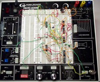
Description: This circuit runs on a single +5 Volt supply and drives a speaker directly. The sound that's heard originates from a 555 timer in one-half of the dual-555 chip (U1), the 556. This 555 circuit drives a 4024 CMOS 7-stage binary counter U2, which produces 7 subharmonics below the frequency of the 555 (quiescently set to be around 10 kHz through the resistors and capacitors at pins 1 and 2 of U1). An 8-1 multiplexer/demultiplexer, the 4051 (U3) selects one signal out of the 7 available subharmonics from U2 and the original clock signal from U1, and routes it through an NPN emitter follower bufer (T1), which is able to drive a loudspeaker, producing the sound that we hear (I've provided a line-level audio output as well for jacking into recording device inputs, decoupled with the 1 uF capacitor and buffered by the 1K-Ohm series resistor). Note that driving a loudspeaker directly off the Class A amplifier that T1 forms isn't good form without isolating the speaker from the transistor with a big (e.g., 1000 uF or more) capacitor (remember that T1 would still need an emitter resistor for DC bias), as the 0-5 volt square waves appearing at the transistor output have an average DC voltage of 2.5 volts, which does nothing but heat up the voice coil in the speaker. I get away with it here as the voltages are so low and the speaker isn't of high quality, but note that it's very poor form.
Comments
You need to be logged in to add a comment.