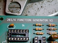
Buchla 281 Clone
Voltage controlled AD/ASR Envelope Generator
Courtesy/Thanks to: Toppobrillo
Description: Topp over at the Electro-music.com forum has made a neat PCB for soldering your own Buchla 281 AR/ASR. Read below and much much more on elektro-music.com
From Toppobrillo's homepage:
This page is here to supplement the information covered in the 281 Clone thread at electromusic.
com. Please read through the thread, you will likely find your question[s] answered there.
The Clone PCB
The Original Buchla 281 Module is made up of 4 independent Function Generators, A,B,C and D- with A&B
and C&D tied together in the bottom section functions, quadrature and ors [peak]. The 281 Clone PCB is
actually 1/4 of a 281, and can be used alone or in conjunction with other boards. The Clone PCB can be built
as either "A" or "B" board described above.
The 281 Function Generator
...Operates like most envelope generators, it's operation is as follows: An appropriate signal at the trigger
input causes the generator to ramp upwards from 0 to 10V at a rate set by the "attack" control and input.
Depending on operation mode, once it reaches 10V, it is either held steady by a gate signal, pending release,
or enters the decay phase instantly [depending on operation mode] and then ramps downward towards 0V
at a rate specified by the setting of the "decay" control and input. At any point in the "decay" cycle, the
generator can be retriggered. Once the cycle is complete, the "end pulse" output will produce a narrow
pulse.
The output function is linear, however, the rate [slope] responds to applied control voltage in an exponential
manner. Applied positive voltages will cause the generator to ramp more slowly- while voltages that are less
positive than the voltage at the control pot's wiper will cause the generator to ramp more quickly. These
voltages average together.
Comments
You need to be logged in to add a comment.